
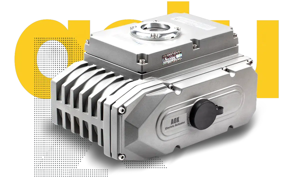
Electric actuator troubleshooting should begin with the fault indication, local or remote operating mode, available power and the valve’s mechanical condition. Repeatedly resetting a trip or raising the torque setting can hide the cause and risk damage to the valve assembly.
This guide helps maintenance teams organise a fault investigation. Use the exact actuator’s manual and wiring diagram for the actual checks and settings. Electrical testing belongs with qualified personnel, and intrusive work requires the plant’s isolation procedure.
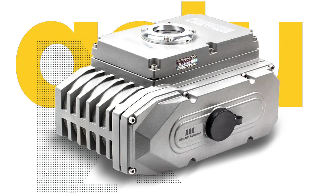
1. The actuator does not respond
Record the display status and any fault code before resetting equipment. Check whether the selector is in local, remote or stop mode and whether the requested command is permitted by the plant interlocks.
An illuminated display does not prove that the motor supply is available. Some assemblies have separate control and motor supplies. Ask the electrical team to verify the circuit against the wiring diagram.
Also establish whether the issue affects one actuator or several. A shared supply or control problem may explain multiple failures.
2. It works locally but not from the control room
If local operation works, investigate the remote-command path. Check the remote selector, PLC output, permissives and the actuator’s configured control mode.
For a networked installation, record communication alarms and verify the approved addressing and configuration. For hardwired controls, compare the actual command with the circuit requirements.
Do not replace the motor simply because the SCADA screen shows no movement. First determine whether a valid command reaches the actuator.
3. The actuator trips before reaching the end position
A torque or thrust trip can indicate resistance in the valve or drive train. Possible causes include deposits, misalignment, a damaged gearbox or changed process conditions.
Record where the trip occurs and whether it happens while opening, closing or both. Compare the operating conditions with the original selection data.
Do not increase protection settings without confirming the valve’s permitted loading and the manufacturer’s instructions. A larger setting can transfer the problem to the stem, coupling or seat.
4. The motor overheats or trips thermally
Review operating frequency, repeated reversals, ambient temperature and mechanical load. A thermal trip may be related to a control loop demanding too many corrections or to a valve requiring unusually high effort.
Allow the prescribed cooling period and investigate the cause before restarting. Do not bypass thermal protection to keep the process moving.
If the duty has changed since installation, check whether the actuator still suits the application.
5. The position indication disagrees with the valve
Determine what the displayed position represents. Actuator travel indication may not confirm the valve’s actual position if the coupling has slipped or a drive component is damaged.
Inspect the mechanical connection under the approved isolation conditions. Then verify travel calibration and feedback scaling according to the manual.
Confirm the physical open and closed positions before accepting a calibration. Incorrect feedback can make a control-room display appear normal while the valve is partly open.
6. The valve hunts around the requested position
Hunting is repeated movement around the target. Review the command stability, feedback, deadband, mechanical backlash and process-controller tuning.
Separate a changing process command from a positioning fault. Record the requested position and reported position together over time where the controls system permits it.
Avoid adjusting several parameters at once. Make authorised changes in a controlled sequence and retain the previous settings.
7. Moisture or corrosion appears inside the enclosure
Inspect cable glands, unused entries, cover seals and the installation’s exposure. Water can enter through poorly sealed cable arrangements even when the enclosure itself has a suitable rating.
If fitted, verify the anti-condensation heater arrangement against the documentation. Do not energise visibly water-damaged equipment until it has been assessed.
After repairs, restore the specified enclosure sealing and record what failed. Replacing electronics without correcting the entry path can lead to another failure.

What to send with a technical support request
Include the actuator model and serial number, valve tag, photographs, fault code, wiring drawing, operating mode and the point in travel where the fault occurs. Add recent changes to pressure, medium, controls or maintenance.
These details help distinguish actuator, valve, installation and control-system problems before parts are ordered
Frequently asked questions
Should I increase the torque setting when the actuator trips?
Only after an authorised technical review confirms the cause, permitted valve loading and correct setting. A trip may be protecting the assembly.
Why does the actuator work locally but not remotely?
The remote command, operating mode, interlocks or communications may prevent movement. Check the control path before assuming a motor fault.
Does an open indication prove the valve is open?
Not necessarily. A damaged or slipping connection can disconnect actuator indication from actual valve position.
Ask KVC Africa for technical support
For help with your valve automation application, send KVC Africa the equipment details and fault information. Our team can discuss the assessment, fitment or commissioning support required.
Send your fault details: sales@kvcafrica.co.za | 016 023 0276.
