
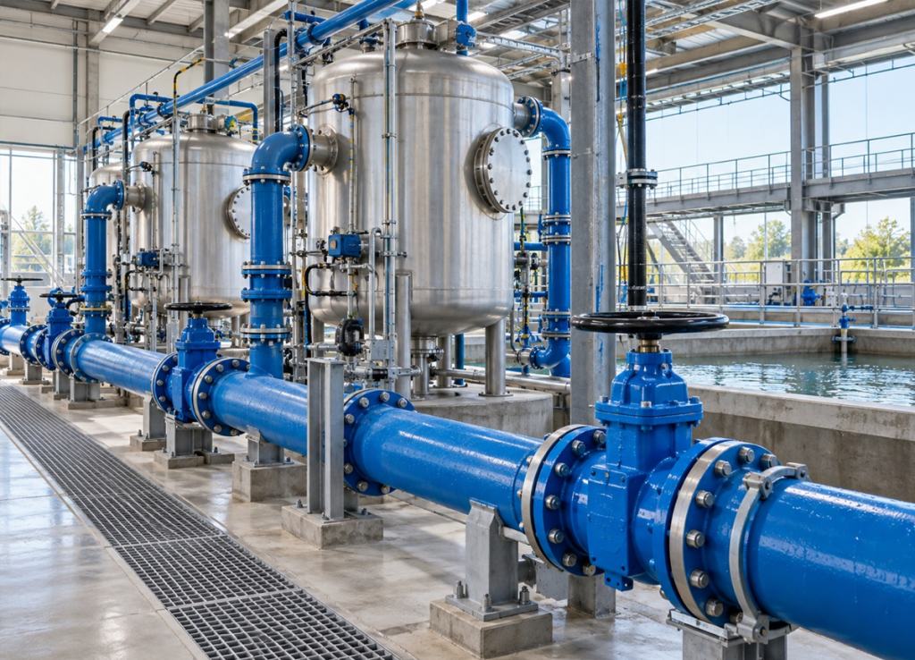
Water Valve Automation: A Worked Electric Actuator Retrofit Case Study
Illustrative engineering case study: this example uses assumed application data to explain a retrofit assessment. It does not describe a completed customer installation or measured operating results.
Water valve automation can introduce remote operation without replacing every existing valve. This worked example considers a manual butterfly valve on a clean-water line at a South African industrial site. It follows the decisions needed before an actuator can be selected and commissioned.
Application brief
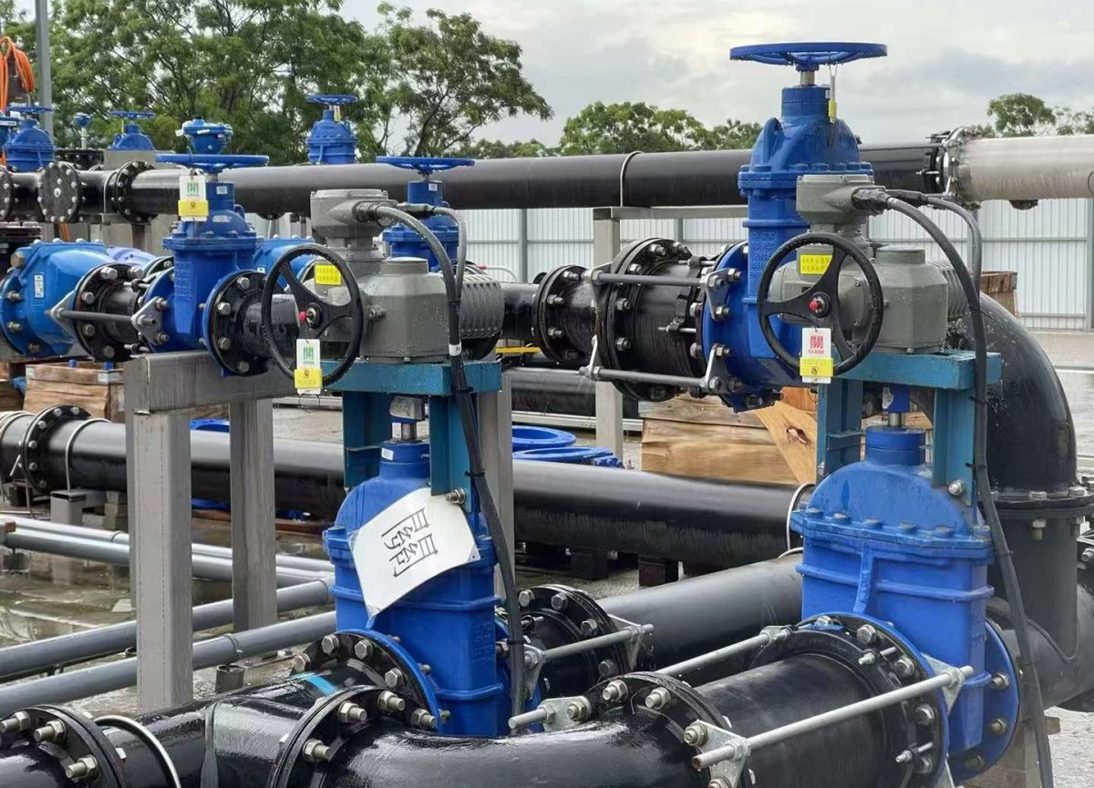
The assumed installation has a DN200 butterfly valve used for occasional isolation. The project requires remote open-close commands, open and closed status, local operation and access to manual override.
For this example, assume the valve is mechanically sound, the drive connection is accessible and the available supply is 230 V AC, single-phase, 50 Hz. Maximum differential pressure is assumed to be 5 bar. The valve manufacturer’s maximum required operating torque at the specified conditions is assumed to be 180 N·m.
These values are example inputs. They must be replaced with verified valve and site data for an actual selection.
Challenge: automate the valve without creating a weak drive train
The central question is whether the existing valve can accept the actuator’s output through a suitable mounting bracket and coupling. A compatible bolt pattern alone does not resolve the stem limits, drive engagement or alignment.
The process team must also define a suitable travel time. The valve should not be selected to close as quickly as possible without considering pressure transients in the water line.
Step 1: inspect the valve and document the interface
A retrofit assessment would record valve identification, leakage, mechanical condition and full travel. Photographs and dimensions would establish mounting access, stem geometry and cable-entry space.
If inspection found seat damage, excessive resistance or an unsuitable drive connection, the project would pause for repair or evaluation of a replacement valve assembly.
Step 2: calculate an illustrative torque requirement
Assume, for this example only, that the agreed application sizing factor is 1.5 and has not already been included in the valve manufacturer’s torque value.
Illustrative sizing requirement = 180 N·m × 1.5 = 270 N·m.
A nominal 300 N·m actuator could therefore be considered for further review. This calculation identifies a candidate rating; it does not establish the final model or protection setting. The 1.5 factor is an example assumption, not a universal sizing rule.
The engineer would still verify rated output at the actual supply and duty, the valve’s maximum permitted torque, the bracket and coupling capacity, and the correct seating method. The actuator’s torque protection, where provided, must be set according to the valve and actuator instructions, rather than simply to the candidate’s maximum rating.
Step 3: review a suitable AOX configuration
An AOX quarter-turn arrangement could be evaluated against the approved torque, supply, mounting and control requirements. KVC Africa’s AOX-R range includes quarter-turn options, but the exact configuration must be confirmed from current technical documentation.
The review would establish enclosure suitability, manual operation, command inputs, status outputs and access for maintenance. Any exposure to flooding, corrosive atmosphere or a hazardous area would require a separate specification check.
For this example, power-loss behaviour is assumed to be hold-in-position and must be accepted by the process engineer. If the process requires automatic closure during a power failure, the proposed conventional arrangement must be reconsidered.
Step 4: define commissioning acceptance
The handover test would confirm actual valve movement, correct end positions, local and remote operation, and status feedback to the control system. It would also verify the agreed travel time and relevant interlocks.
Protection settings and mechanical stops would be checked against the approved instructions. Representative operating conditions should be included where practical and safe. A no-load test alone cannot verify performance at the maximum application load.
Expected capability and results to measure
If the assessed assembly passes installation and acceptance testing, its intended capability is remote isolation with local operation and end-position indication. No downtime reduction, labour saving or financial return is claimed in this example.
An actual project should record operating cycles, failed commands, intervention time and maintenance work before and after installation. Any savings calculation should identify its baseline, measurement period and included costs.
FREQUENTLY ASKED QUESTIONS
Is 300 N·m the correct actuator for every DN200 butterfly valve?
No. The example follows assumed load data. Actual torque depends on the valve design, pressure, medium and condition.
Can this example be used as an installation specification?
It illustrates the assessment process. Final selection requires verified valve limits, site data and approved engineering review.
Plan your water valve automation project
KVC Africa offers site surveys, actuator sizing and fitment and commissioning services. Send your valve data and operating requirements to discuss whether a retrofit or a complete assembly is appropriate.
Request a retrofit assessment: sales@kvcafrica.co.za | 016 023 0276.
