
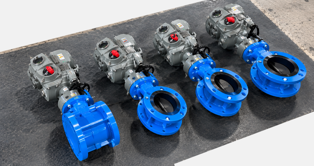
A modulating electric actuator moves a valve to intermediate positions in response to a control signal. Unlike an open-close actuator, it can position the valve between its end stops. Selecting a modulating electric actuator requires attention to both the control interface and the frequency of movement.
In water treatment and industrial process systems, this distinction matters whenever the plant needs to regulate a process rather than simply isolate a line.
Open-close and modulating control: what is the difference?
Open-close operation moves a valve to its open or closed position when commanded. Modulating control requests an intermediate position and uses actuator position feedback to move towards that request.
That actuator position loop is different from the plant’s process-control loop. A flow meter, pressure transmitter or other process instrument may provide the feedback used by the PLC to decide the required valve position.
An actuator can accurately reach a requested position while the process remains poorly controlled. Valve selection, hydraulic conditions and controller tuning still matter.
How does a 4–20 mA command work?
For a linear mapping configured with 4 mA as 0% position and 20 mA as 100%, the requested position is:
Position (%) = (signal in mA − 4) ÷ 16 × 100.
This gives 4 mA = 0%, 8 mA = 25%, 12 mA = 50%, 16 mA = 75% and 20 mA = 100%. The direction can be reversed if the actuator and plant configuration require it. Confirm the actual mapping during commissioning.
The command signal and position-feedback signal are separate functions. A 4–20 mA input does not automatically mean the selected actuator includes a 4–20 mA output. Check the ordered configuration and wiring diagram.
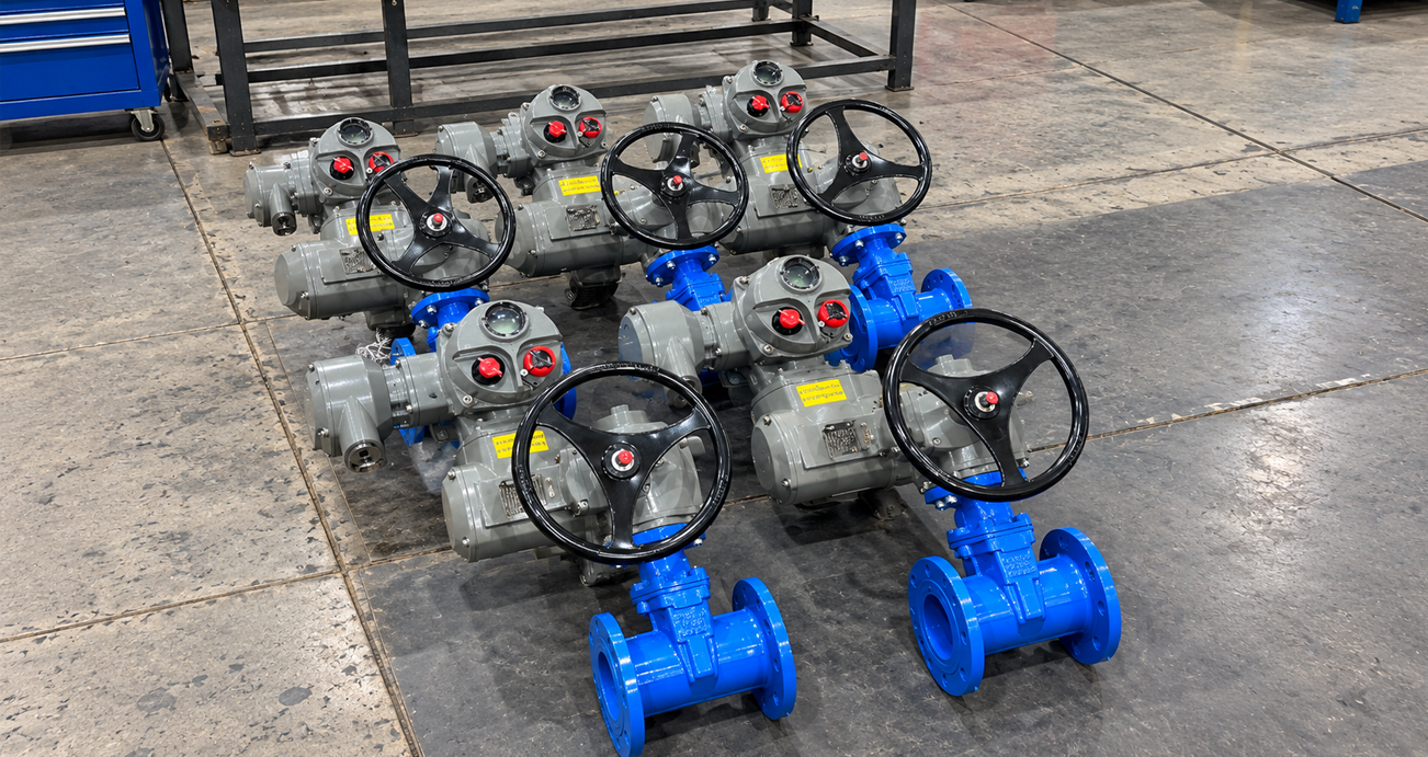
Why 50% valve position does not mean 50% flow
Valve opening and flow are not generally proportional. The valve’s inherent flow characteristic, the pressure drop across it and the connected system determine the resulting flow.
A butterfly valve at half travel, for example, should not be assumed to deliver half of the maximum flow. The process engineer must check that the valve has a useful control range for the application.
For an RFQ, provide the required minimum, normal and maximum flow, relevant pressures and the medium. These inputs help assess the complete valve-and-actuator solution.
Check the actuator’s modulation duty
A signal interface is not a duty rating. Confirm the permitted starts per hour, motor operating time, load and ambient conditions for the exact actuator size and configuration.
Frequent corrections can generate heat and increase wear. An actuator selected for occasional isolation may not be appropriate for a continuously adjusting process loop.
Also review deadband: the small difference between requested and actual position that the controller allows before initiating movement. An excessively narrow setting may encourage repeated corrections. Too wide a setting can compromise control. Set it to suit the process and manufacturer’s guidance.
Define power-loss and signal-loss behaviour
Loss of electrical power and loss of the control command are different events. Specify what the valve must do in each case, and confirm the available functionality.
Options may include remaining in position or moving to a defined position, but powered movement depends on the actuator design and an available energy source. Do not treat ordinary self-locking as an automatic fail-safe return function.
For a critical process, the required safe response should be defined by the plant’s engineering team before equipment is selected.
Commission the complete control loop
Verify the configured signal range, movement direction, travel limits and feedback scaling. Check several intermediate positions and confirm that the displayed position agrees with the actual valve movement.
Then test the process response under representative conditions. Confirm interlocks, alarm behaviour and the agreed response to signal loss. Record the final settings so future adjustments are traceable.

FREQUENTLY ASKED QUESTIONS
Can an open-close actuator be used for modulation?
Only if the exact actuator and controls are approved for the required positioning duty. A control-board change alone does not establish suitability.
Is a 4–20 mA signal the actuator’s power supply?
It is typically the command interface. Confirm the separate motor and control power requirements on the selected unit.
Does a modulating actuator control flow directly?
It controls valve position. The resulting flow depends on the valve, pressure conditions and process-control arrangement.
Specify your modulating actuator with KVC Africa
Send your valve data, control signal, feedback requirements, expected movement frequency and power supply to KVC Africa. We can help review a suitable AOX configuration and the commissioning requirements for your application.
Request a specification review: sales@kvcafrica.co.za | 016 023 0276.
